From aerodynamic design to carbon manufacturing and hub fitting, explore how E-Props propellers are engineered and built in Sisteron, France.
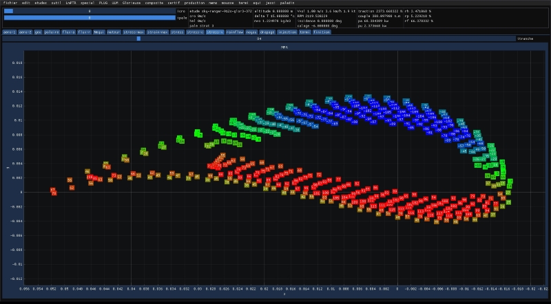
LUKY software stress analysis

Design & LUKY software

Profile optimization by artificial intelligence, propulsion theory, tests, moment of inertia, efficiency, EASA certification.
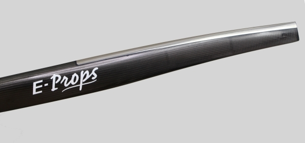
Titanium leading edge protection

Manufacturing

RTM carbon process, Titanium leading-edge protection, balancing, tracking, vibrations.
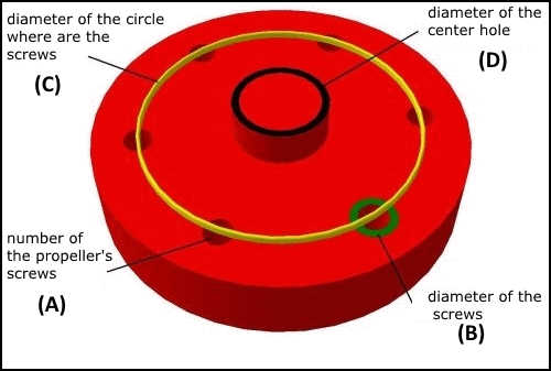
Hub drilling diagram

Hub drilling patterns

Standard and optional drilling patterns available for fixed- and adjustable-pitch propellers.

Propeller basics

A propeller is more than “diameter × pitch”

“We need a 26 × 14.” We hear this a lot. But diameter and pitch do not define a propeller, just as span and angle of incidence do not define a wing. Two wings with the same span and the same incidence can carry very different loads: one may be narrow, the other wide. You also need the chord, the airfoil, the twist…

A propeller is a rotating wing. It needs the same full description.

What really defines a propeller

  1. Diameter. It sets the disc area, and therefore efficiency and tip speed (noise, compressibility).
  2. Number of blades. More blades absorb more power in the same diameter, but each blade works in the wake of the others.
  3. Pitch distribution (twist). “14 inches of pitch”, but measured where? Pitch changes along the blade. By convention it is given at 75 % of the radius, but not every manufacturer follows that rule, and many blades do not have a constant pitch.
  4. Chord distribution (blade planform). This is the forgotten parameter, and it is the wing chord of our example. At the same diameter and pitch, a wide blade absorbs much more power than a narrow one. With a wide blade, the engine may not reach its RPM. With a narrow one, it over-revs.
  5. Airfoils along the blade. Camber and thickness set how the blade really works. A cambered airfoil still produces lift at zero angle, so the aerodynamic pitch is greater than the geometric pitch. Two “14-inch” propellers can behave like a 13″ and a 16″.
  6. Thickness distribution. It is driven by strength, but it also affects drag, especially near the tip.
  7. Tip and root shape, sweep. These matter for noise, tip losses and the transition to the hub.
  8. Material and stiffness. Under load a blade bends and twists, so its pitch changes in flight. Mass and inertia matter too. On a direct-drive engine, especially a 2-stroke, they set the torsional vibrations of the whole engine-propeller system.
  9. Hub and mounting. Drilling pattern, centring bore, hub thickness, direction of rotation, tractor or pusher.

And the propeller only makes sense with its aircraft

Even a perfectly defined propeller is only “good” for one operating point. To design yours, we also need the engine (power and RPM, maximum RPM, gearbox or direct drive), the flight speeds (take-off, climb, cruise, maximum), the aircraft mass and the space available.

This is why we design every E-PROPS propeller with our LUKY software, from the data of your aircraft (see how we work).

Diameter × pitch is a name, not a design.
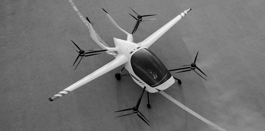
E-Props fixed pitch carbon propeller